
- #Test serial connection between two arduinos how to#
- #Test serial connection between two arduinos software#
- #Test serial connection between two arduinos code#
- #Test serial connection between two arduinos Pc#
Make sure that your Arduino board is attached to your computer via USB to enable serial communication through the serial monitor window of the Arduino Software (IDE). After that, it does the same on the second virtual port (portTwo). The board listens on one virtual port (portOne) until it has read all available data. In the example below, digital pins 8 and 10 on your Arduino board are used as virtual RX serial lines. This can be extremely helpful when the need arises to communicate with two serial enabled devices, or to talk with just one device while leaving the main serial port open for debugging purpose. For stuff like that, you'll have to ask someone more knowledgeable than I.Arduino boards have built in support for serial communication on pins 0 and 1, but what if you need more serial ports? The SoftwareSerial Library has been developed to allow serial communication to take place on the other digital pins of your boards, using software to replicate the functionality of the hardwired RX and TX lines. Arduino Serial Communication: Many Arduino projects rely on transmitting data between several Arduinos. They aren't rooted in textbooks or efficiency.
pc< (serial)>arduino< (http via router)>arduino< (serial)>pc.#Test serial connection between two arduinos Pc#
Below is a possible test setup using a pc and router.
#Test serial connection between two arduinos code#
Like I said, both of these methods are approaches that I just came up with. You would need to modify the code from what it does now to communicate between two arduinos instead of between an arduino and typical server. Again, check out the Serial or communication label. If you want examples of where I have done this, I know one of these methods is used in the serial HC-SRO4 controller post. Just make sure that whatever your identifier is, it will never be included in the data packets. You get the idea.Īnother way, I have done the same thing except with just an identifier to mark the first sensor (in this case 128). Then I know if I read a byte and its 105, the next byte I read will be sensor 1. For instance, I map the sensors to a value from 0-100 then I'll send this.ġ05 106 etc. I've done stuff like sending an identifier before each value. Google may provide better answers, but I can tell you how I've done it.

Well I'm not a software programmer, so I don't know the "correct" way of doing it. It's more of a master-slave relationship. Note that the Tx and Rx labels are a bit arbitrary in this one. The Rx then adds 5 to the integer an sends it back to the Tx.
#Test serial connection between two arduinos how to#
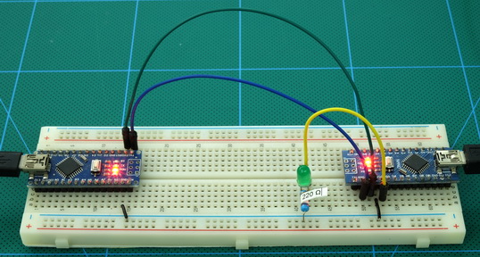
The main task Is How to upload code in ESP-01 Using Arduino. This one takes an integer value from a user input through the Serial Monitor and then sends it to the Rx Arduino. Serial Communication Between Arduino and ESP-01: In This Tutorial we will see the Serial Communication Between the Arduino and ESP-01. Well that's great and all, but I want to communicate both ways. Just make sure you wire in the common ground as always. In fact, if you had two "real" Arduinos with an FTDI or similar, you wouldn't even need to do that. It's the same as you just did except in reverse the two boards. The next program blinks the LED on the Rx board a specific number of times entered through the Serial Monitor connected to the Tx board. By the way, if you're wondering where I got that super cool Tx Arduino, check out THIS post. This might be avoided if you put a resistor in between the 2 boards, but I have not tried. Leaving them connected caused an error for me. Note that you may need to connect these pins after you load the program on the Arduino (since you are using that pin to communicate with the computer via the USB to serial chip). Then connect a common ground between the two. To wire it up, simply connect Tx (probably pin 1) of the Tx board to the Rx (probably pin 0) of the Rx board. Well that doesn't work because that displays the ASCII character and not the integer value.

A momentary switch, button, or toggle switch. The only unexpected detail is the parseInt(). This example shows you how to monitor the state of a switch by establishing serial communication between your Arduino and your computer over USB. You can get mine HERE, but I would encourage anyone to try to write it yourself.

I only have one Arduino with a working USB to serial interface, so I used it as the Rx. The receiving Arduino then prints that number to the COM port where I can see it. One Arduino transmits one integer every second counting from 1 to 10. You might want to read up on the different commands you have there. Well let's get to it.įirst things first, HERE is the Arduino playground page for serial communication. I expected there to be more hitches, but it turned out to be pretty straight forward. I want to explore the different ways to communicate with and between Arduinos.įirst up is serial communication. I wanted to know more about inter-Arduino communication, so I did this project.


 0 kommentar(er)
